
We introduced John Doyle’s remarkable invention in our previous post – see link below. There, we defined the various parts, and how a pump replenished the ‘excitant’ fluid. Today we move on to describing the operation of the world’s first flow battery in more detail. Time may yet prove this was one of the most important moments in energy storage history.
Operating Principles of the World’s First Flow Battery
PART OF THE FLOW BATTERY
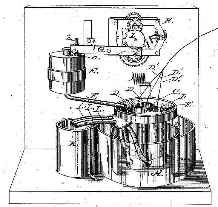
- ‘A’ is a plain jar containing ‘B’, a ‘cleft zinc plate that connects to the first circuit wire.
- Two or more porous jars ‘C’ sit within this, each containing a ‘D’ electro-negative plate.
- Each electro-negative plate has a coupling wire D1. These connect to the second circuit wire.
- ‘E’ is a suitable reservoir for ‘excitant’ supply. A feed-pipe ‘F’ connects it to the flow battery.
- There, the ‘excitant’ flows via a funnel E1 or ‘hopper’ sealed onto the mouth of the porous jars.
EXCITANT DELIVERY MECHANISM
- The top of the reservoir ‘E’ contains a protruding tube ‘a’ having a conical bore profile.
- A vertical plug ‘b’ with a matching profile fits precisely into this without possibility of leakage.
- The plug locates inside the arm of a ‘vertically-vibrating’ lever ‘G’ exerting sufficient fulcrum.
- A clockwork mechanism ‘H’ automatically moves this fulcrum via a single or double cam ‘I’.
- This cam depresses the lever ‘G’ intermittently, causing the plug ‘b’ to lift on each occasion.
- This allows air to enter reservoir ‘E’ and in turn allow an amount of ‘excitant’ to enter the porous jars.
- The cam ‘I’ rotates once per hour with a single tooth. This rate increases by adding teeth.
- Waste pipes ‘L’ carry ‘expended or partly-expended excitant’ to a separate storage vessel ‘K’.
- This liquid may then be replenished by addition of chemicals according to requirements.
We’ll wrap this up in a third article shortly. We do hope you are finding this interesting!
More Information
First Flow Battery By John Doyle


