
Charles S Bradley hardly turns up a Google Search result, except in respect of February 24, 1885. That was the memorable moment when the citizen residing at Yonkers, New York received U.S. Patent 312,802 for a new innovation. We pause on our journey to review the Charles S Bradley secondary flow battery in some detail. Because this is all we know of the man.
Charles S Bradley Secondary Flow Battery Design
Bradley expressed concern in his 1885 patent application about secondary, rechargeable battery performance. Those rechargeable cells were too bulky to justify their limited storage capacity and reliability, he complained. They also took too long to recharge he said, and the energy required to do so was far more than they stored.
KEY PARTS OF THE BRADLEY FLOW BATTERY
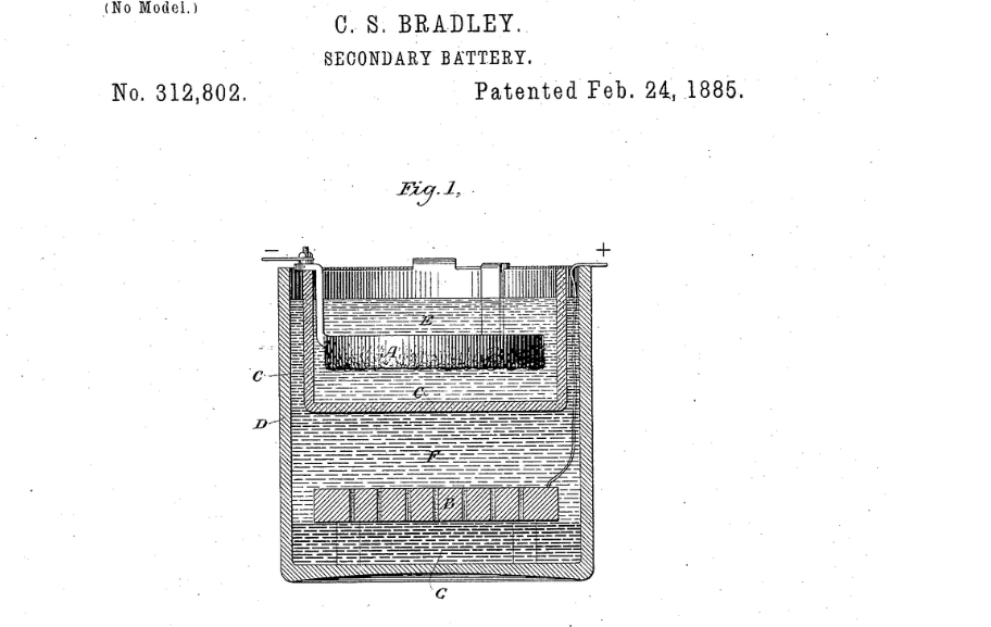
Charles S Bradley’s application claimed it addressed these issues by delivering a convenient, compact, and efficient battery. And moreover, it was capable of storing the maximum amount of energy with the least possible weight. Referring to the above drawing, we see a vessel ‘D’ with a perforated carbon plate ‘B’ towards the container bottom, but not on it.
A porous cell ‘C’ locates at the top of vessel ‘D’. A zinc plate ‘A’ suspends inside this porous cell by means of ‘hangers’ or some other convenient arrangement. A ‘nearly saturated solution of zinc bromide’ fills both the surrounding vessel ‘D’ and the porous cell ‘C’. This arrangement ensures the liquid surrounds both carbon plate ‘B’ and zinc plate ‘A’
Charles S Bradley’s Flow Battery Was Good to Go
The patent application pauses at this point to explain the flow battery is ready for charging. This is achieved by connecting the negative pole of a dynamo to zinc plate ‘A’. And then joining the positive terminal of the dynamo to carbon plate ‘B’ and firing it up. We’ll be back shortly with more detail about this amazing idea.
More Information
First Flow Battery By John Doyle
Flow Battery Power Airship La France


